Digital Potentiometer (Digital Potentiometer), also known as CNC Programmable Resistor, is a new integrated circuit for CMOS digital and analog mixed signal processing that replaces traditional mechanical potentiometers (analog potentiometers). The digital potentiometer adopts the numerical control method to adjust the resistance value. It has the advantages of flexible use, high adjustment precision, no contact, low noise, low fouling, anti-vibration, anti-interference, small size and long life. It can be replaced in many fields. Mechanical potentiometer.
Digital potentiometers typically have a bus interface that can be programmed by a microcontroller or logic circuit. It is suitable for a variety of programmable analog devices, such as programmable gain amplifiers, programmable filters, programmable linear regulated power supplies, and tone/volume control circuits. It truly implements "putting analog devices on the bus" (ie, the microcontroller passes The analog function block of the bus control system) is a new design concept.
At present, digital potentiometers are rapidly being promoted at home and abroad, and are widely used in testing instruments, PCs, mobile phones, household appliances, modern office equipment, industrial control, medical equipment and other fields.
1 Basic working principle Since the digital potentiometer can replace the mechanical potentiometer, the two have similarities in principle. The digital potentiometer belongs to the equivalent circuit of the integrated three-terminal variable resistance device, as shown in Figure 1. When the digital potentiometer is used as a voltage divider, its high-end, low-side, and sliding terminals are represented by VH, VL, and VW, respectively, and when used as adjustable resistors, they are represented by RH, RL, and RW, respectively. 
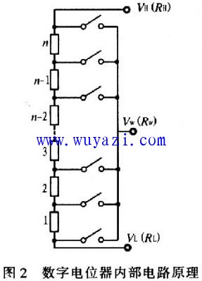
Figure 2 shows the internal simplified circuit of the digital potentiometer. N resistors of the same resistance are connected in series. The two ends of each resistor are connected via an analog switch composed of a MOS transistor as a tap of the digital potentiometer. This analog switch is equivalent to a single-pole, single-throw switch, and only one analog switch can be closed at a time under the control of a digital signal, thereby connecting each node of the series resistor to the wiper. 
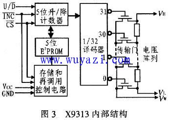
The digital control part of the digital potentiometer includes four digital circuit modules such as an up-down counter, a decoding circuit, a save and restore control circuit, and a non-volatile memory. The up/down counters of the serial input and the output can be counted up/down under the control of the input pulse and the control signal, and the counter directly supplies the accumulated data to the decoding circuit to control the switch array, and also transfers the data to the internal memory. save. When the external counting pulse signal is stopped or the chip select signal is invalid, only one output of the decoding circuit is valid, so only one MOS transistor is selected to be turned on.
The memory of the digital control part is a kind of power-down non-volatile memory. When the circuit is powered off again, the original control data is still stored in the digital potentiometer, and the resistance between the middle tap and the two ends is still The last adjustment result. Therefore, the digital potentiometer has the same effect as the mechanical potentiometer. However, since the operation of the switch adopts the method of “connecting first and then disconnectingâ€, the resistance value of the digital potentiometer may be different from the expected value during the period when the input count is valid, and the expected value can be achieved only after the adjustment is completed.
As can be seen from Figure 2, the digital potentiometer has two important differences from the mechanical potentiometer: 1) During the adjustment process, the resistance value of the digital potentiometer does not change continuously, but has the desired output after the adjustment is completed. . This is because the digital potentiometer uses the MOS tube as the switching circuit, and adopts the control method of “first open and then closeâ€: 2) the digital potentiometer cannot realize the continuous adjustment of the resistance, but can only be the smallest on the resistance network in the digital potentiometer. The resistance value is adjusted.
2 Typical application of digital potentiometers Digital potentiometers are widely used, and there are many types according to different classification standards, but the basic principles are similar. Here, the digital potentiometer X9313 of the three-wire add/subtract interface is taken as an example to introduce the digital potential. Application.
2.1 Internal structure and working principle X9313 is an industrial-grade 32-tap digitally controlled potentiometer with a maximum resistance of 10kΩ. It is available in 8-pin package with DIP, OIC and FSSOP. The internal functional block diagram of the X9313 is shown in Figure 3. It consists of an input part, a 5-bit E2PROM, a memory and recall circuit, a 32-select decoder, a 32-channel analog switch consisting of a MOS field effect transistor, and a resistor array. The input part is a 5-bit up/down counter connected to the MCU via a three-wire add/drop interface (), which works like a up/down counter, the output is decoded, and the control is turned on by an electronic switch, so that the resistor array is A point on the top is connected to the sliding output. The resistor array consists of 32 equivalent resistors and associated electronic switches. Depending on the level of the console, the contents of the counter can also be stored in non-volatile memory for subsequent use. 
The two top leads are connected to VH and VL, respectively, and the middle tap is VW. It is 3 control terminals, among them, the chip select terminal, when it is low level, X9313 is selected. The signal that can be received at this time. The counter is incremented or decremented by one on the falling edge. If the sliding end slides in the VH direction, the resistance between VW and VH is reduced by a step. Conversely, if the sliding end slides in the VL direction. After the counter output is decoded, after 32 is selected, the position of the wiper is moved along the resistor array. When the counter reaches an extreme (00000 or 11111), it will not loop back. It will automatically change from 00000 to 1111l, or from 11111 to 00000, that is, when it is high and also high, the value of the counter. Stored in non-volatile memory, when the system is powered up, the device automatically sends the value in the non-volatile memory to the counter as the output of the counter.
2.2 Typical Applications 2.2.1 Manual Control Voltage Regulation Circuit Figure 4 shows. Connect VH to +5V and VL to ground. An adjustable voltage of 0 to +5V is output from the VW terminal. R1 and R2 are pull-up resistors. As soon as the switch S1 is pressed, the output voltage rises, and the voltage rises by 0.05V each time, up to 5V. If you press and hold S2, it is low level. At this time, press S1 to decrease the voltage by 0.05V every time. 
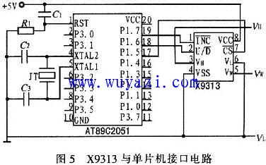
2.2.2 Interface Circuit of X9313 and Single Chip Microcomputer The commonly used AT89C2051 single chip microcomputer is taken as an example to introduce the interface circuit of digital potentiometer and single chip microcomputer. The three control terminals of the potentiometer are connected to P1.7, P1.6 and P1.5 of AT89C2051. A power-on reset circuit is formed by R1 and C1, and a crystal oscillator circuit is formed by C2, C3 and a quartz crystal JT. Because the I/O port of the MCU has a pull-up resistor inside, the above control terminals are all high level when the power is turned on, and the potentiometer is in the standby state. The application is the same as the above example. 
The relevant program code is as follows: 
The above program implements UD to a high level. At this time, 50 pulses are sent to the digital potentiometer, and the resistance is increased so that the voltage between the high and low terminals is 2.5V. The digital potentiometer is controlled by a single-chip microcomputer to control the size of the digital potentiometer, thereby conveniently and accurately changing the resistance value. However, in practical applications, attention should be paid to the analysis and compensation of the error of the digital potentiometer.
3 Conclusion Digital potentiometers are a promising new type of electronic device that can replace traditional mechanical potentiometers in many areas. The advantages are: high adjustment precision; no noise, extremely long working life; no mechanical wear; data can be read and written; configuration register and data register; multi-level storage function. It is widely used in instrumentation, computer and communication equipment, household appliances, health care products, industrial control and other fields. Any type of resistor that requires parameter adjustment and control can be used to form a programmable analog circuit using a digital potentiometer. However, in actual use, special attention should be paid to the resistance adjustment error of the digital potentiometer, which may be different due to different application occasions. Therefore, in practical applications, it is better to use the A/D conversion circuit to accurately measure it and compensate it with a single-chip microcomputer.
LED Laser lamp,Full color led laser lamp
Kindwin Technology (H.K.) Limited , https://www.ktl-led.com