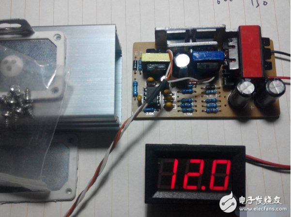
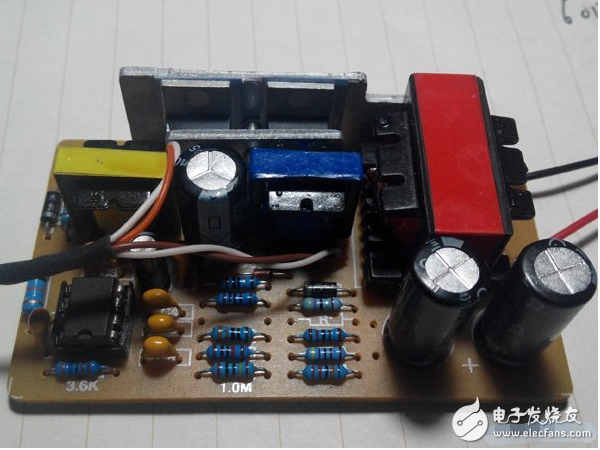
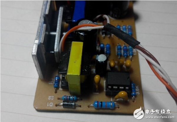
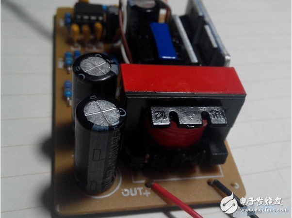
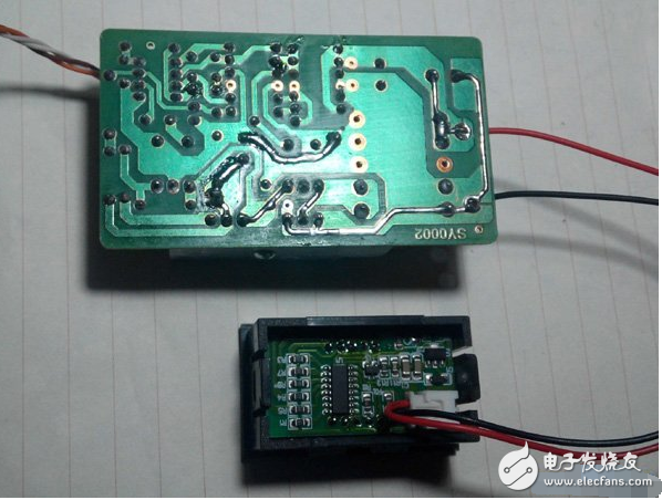
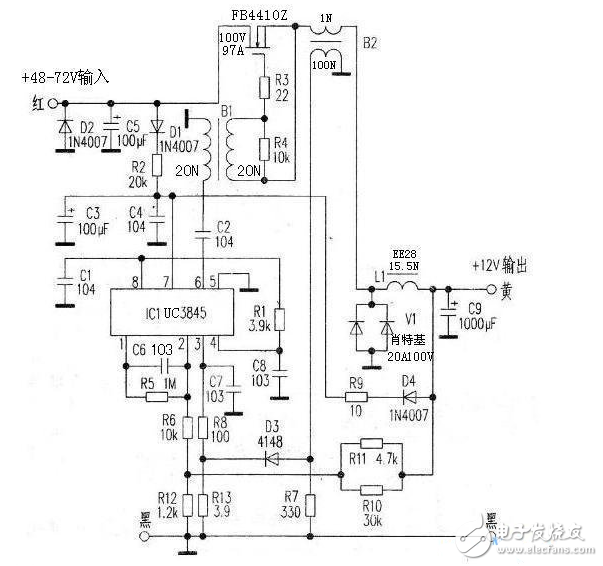
Nowadays, electric vehicles are all 48V or 72V DC converters, which convert the voltage to 12V, and then the 12Vs are used for the lamps and speakers. The electric car 72v turns 12V. The 72V electric car headlight is 12V. Is this 12V converted from the electric car controller? Still have a separate converter? If it is converted from the electric vehicle controller, connect the xenon headlights to the 12V line. (Xenon headlights are regular, with a ballast.) The xenon headlights start current is 3.2A, the highest. 10A. Controller 72V1200W 12-tube controller current limit 30A. Battery size 72V/20Ah. Can you burn the controller? Need to install a 72V converter 12V converter? The electric car's 72V to 12V power is basically from the converter, so no matter what light bulb you install, it is impossible to burn the controller. But if you install the light bulb, it may burn your headlight base. The replacement Xenon headlights are no problem from the data. But from the actual experience, it is not possible. First, the quality and bearing capacity of the cable and the lamp holder will not be deformed and burned out. Second, the design inside the lampshade is very amateur and unqualified, that is, it will not be deformed in a long time. The controller will not burn out because the power cord is usually connected to the battery. Therefore, the third article appears, and the battery connector is also easily damaged. So I recommend not to modify If you really need it, you can buy a 12v cold light, which can be found on Taobao. Adding an effect is not bad, and the fault will be slightly less. At present, there is no post on the forum that introduces the electric vehicle converter. Just before the National Day, I bought a spare part on the Internet. It belongs to the classic circuit of the three transformers. It is not difficult. It is better to solder the components on the board. It is easier than DIY. Prepare to add a small circuit board and change it to a constant voltage constant current charger of 12.6V lithium battery. After testing, this board has an input current of only 7mA (no load) at input 60V and output 12V. The load efficiency is 80% to 90%. At the maximum current of 10A, it can reach 120W output power. The whole board layout is a three-transformer classic circuit UC3845 and switching tube excitation transformer Output capacitor and EE28 energy storage inductor Circuit board traces (larger current copper foil should be soldered) Converter circuit schematic 1. Introduction to UC3845: The UC3845 is designed for low voltage applications and is a PWM controller with low voltage lockout threshold of 8.5 volts (pass) and 7.6V (off), input voltage of 12-15V, output voltage of 5V, output current: 200mA, operating frequency up to 500kHz, maximum Power consumption is 1W. Detailed parameters can be found in Baidu search PDF files. 2, working principle: The 48V-72V DC voltage provides the starting voltage to the UC3845 7 pin via D1 and R2. The oscillation frequency is determined by R1 and C8, and the measured frequency is 42KHz. The UC38456 pin output pulse is supplied to C2, and B1 is converted into an AC signal to provide an excitation signal for the switch tube FB4410Z (N-type field tube 100V, 97A). After the switch tube is turned on, the current detecting transformer B2 and the energy storage inductor L1 are supplied with power to the output terminal, and the Schottky pair tube V1 (20A, 100V) provides freewheeling when the switch tube is turned off. The output voltage is divided into two ways: one is divided into R1O, R11, R6, R12 and then enters the UC38452 pin. If the voltage is too high, the UC3845 6-pin output pulse width is narrowed, and the voltage is too low. The UC3845 6-pin output pulse width is widened, so the output is output. The terminal voltage is stabilized at 12V; the other is via D4, R9, C3, C4 to UC38457 to provide a stable supply voltage. When the output current is too large and exceeds the limit value, the voltage induced by B2 enters the UC3845 3 pin through D3 and R8, forcing the oscillator to stop vibrating and protecting the switch tube from damage due to overcurrent.
Battery Connector:Cell phone battery connector Net bookbattery Connector ,Cell Phone Battery Connector.
Power connector, which includes an insulating body and a plurality of terminals, the insulating body has a plurality of holding slots which hold the terminals, the insulating body is additionally provided with at least one tongue piece which isolates the terminals, the terminals are respectively provided with a barb, the terminals are respectively extended outwards on the first side of the barbs with a plurality of contact parts, and the second barb A plurality of wires are fixed at the side; through the above structure, the barb of the terminal can be embedded in the insulation body, and the terminal is easy to assemble, and only needs to be pushed into the insulation body, and there is no short circuit equivalent energy between the terminals.
Battery Connector ShenZhen Antenk Electronics Co,Ltd , http://www.coincellholder.com