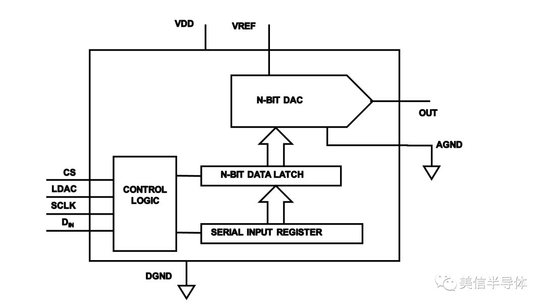
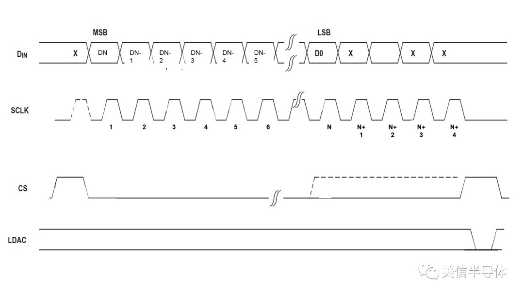
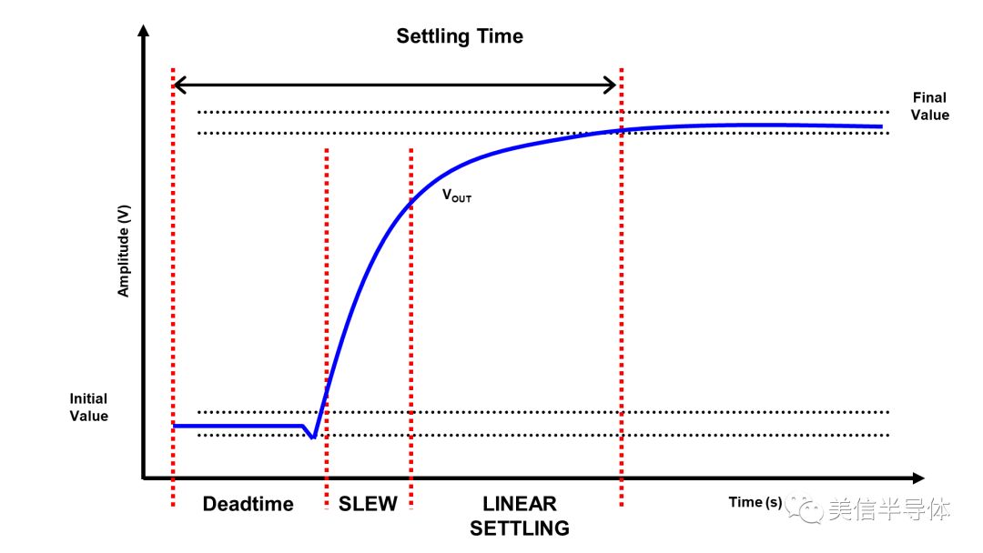
A large number of devices use digital-to-analog converters (DACs) to implement a wide variety of functions. Common applications for high-precision, voltage output DACs include instrumentation, automated testing, and test/measurement equipment. In these applications, the DAC generates a DC voltage or arbitrary waveform. For these circuits, the most challenging part of designing with a voltage output DAC is to really understand how quickly the monster can run within its specified accuracy. If a device has a clock frequency of 50 MHz, what does this mean in terms of voltage output update speed? Or, in addition to knowing the clock frequency, do you need more information? The voltage output DAC adopts FIFO mode, which is first-in, first-out (Figure 1). Typically, the user loads the DAC's input digital data (DIN) into the DAC's internal serial input register and latches the previous data encoding to the N-bit DAC. Figure 1. General block diagram of a high-precision, voltage output DAC When the LDAC (Load DAC) pin is high, the serial data stream, in conjunction with SCLK (serial clock), loads the DAC's serial input register (Figure 2). After the input register is full, a low level of LDAC loads the serial input register into the N-bit data latch. LDAC goes high again and the analog output voltage is output through the OUT pin and settles to its final value. During setup time, the serial input register receives the next code. Figure 2. Common timing diagram for a high-precision, voltage output DAC Ideally, the theoretical throughput rate of the DAC is equal to SCLK/N, where SCLK is the external clock rate and N is the number of DAC bits. For example, for a 16-bit DAC, the maximum clock rate is 50 MHz and the throughput rate is 50 MHz/16, which is 3.125 MHz. This is a terrific DAC throughput! However, this is very unrealistic, especially if you set the analog output voltage to full or rail-to-rail output. In this case, you need time to stabilize the output to its full value. Establishment time is everything So, we still come back to reality. The settling time in high-accuracy applications determines the effective update rate of the DAC, and does not depend on the clock's data rate. The DAC's analog output frequency structure is usually first-order. For larger signals, it is easy to use R/C circuits to model this response. For this circuit, the following formula can be used to describe the analog input/output behavior. VOUT = VIN(1 – et/RC) Equation 1 In the formula: VOUT 模拟 Analog Output Voltage VIN 模拟 Analog input voltage R ➔ DAC output resistance C ➔ DAC Output Capacitor Figure 3 shows the analog signal setup time response for the DAC system, including the dead-time, swing, and linear-creation sections. Figure 3. Theoretical output setup time for the DAC Dead time is the time the DAC uses the data latch register to update the analog output. If a large analog input step occurs, the DAC will enter the swing zone. At the end of the signal response, the final value is ±1/2 LSB of the theoretical final value. The DAC's data sheet will list the setup time indicators. Take the MAX5717 16-bit, 50MHz, voltage output DAC as an example, the settling time is 0.75us. At first glance, it will be assumed that the DAC's throughput rate is 50MHz divided by 16, or 2.33MHz. If you take into account the setup time of the DAC, the actual throughput rate of this DAC is the reciprocal of setup time, which is 1.33MHz. Important work priorities Devices that use intensive DACs require DAC behavior optimization, depending on system requirements. For instrumentation, automated test and test/measurement applications, throughput is the main technical indicator. The details of the DAC precision performance are important, but keep in mind that the setup time is the best indicator that allows you to immediately see if the DAC speed is sufficient for the circuit.
What features you consider more when you choose an university laptop for project? Performance, portability, screen quality, rich slots with rj45, large battery, or others? There are many options on laptop for university students according application scenarios. If prefer 14inch 11th with rj45, you can take this recommended laptop for university. If like bigger screen, can take 15.6 inch 10th or 11th laptop for uni; if performance focused, jus choose 16.1 inch gtx 1650 4gb graphic laptop,etc. Of course, 15.6 inch good laptops for university students with 4th or 6th is also wonderful choice if only need for course works or entertainments.
There are many options if you do university laptop deals, just share parameters levels and price levels prefer, then will send matched details with price for you.
Other Education Laptop also available, from elementary 14 inch or 10.1 inch celeron laptop to 4gb gtx graphic laptop. You can just call us and share basic configuration interest, then right details provided immediately.
University Laptop,Laptop For University Students,University Laptop Deals,Recommended Laptop For University,Laptop For Uni Henan Shuyi Electronics Co., Ltd. , https://www.shuyielectronictech.com

