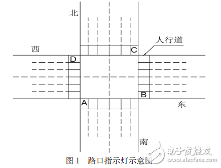
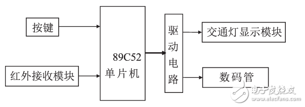
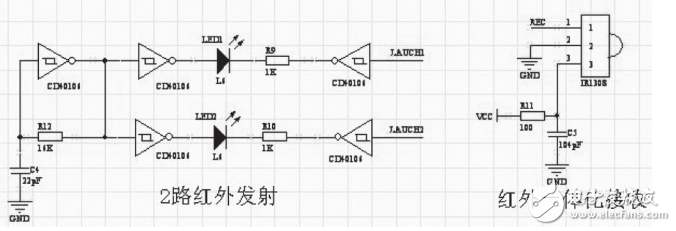
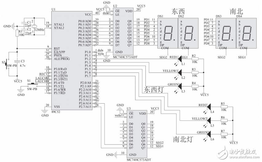
The city roads are intricate and intertwined, and traffic lights are an important command system for urban traffic. As an effective means to control traffic flow and improve road traffic capacity, traffic lights have obvious effects on reducing traffic accidents. However, the traffic volume is changing at any time, while the traditional traffic light mode uses timing control, which is easy to cause traffic jams. The traffic light designed in this paper can convert the traffic light switching time according to the usual peak hours of commuting or commuting. The red light conversion time of the peak hours of the work is set to 40 seconds, and the usual setting is 60 seconds. This can effectively alleviate the time during the commute, because the red light setting time is too long, in order to catch up with the time and red light phenomenon. At the same time, it effectively alleviates traffic congestion. In 1968, the United Nations "Road Traffic and Road Signs Signal Agreement" stipulated the meaning of various signal lights: green light allowed to pass; red light is on, no traffic is allowed; yellow light is on, prompting people to pay attention to red, the state of green light is about to switch. For the convenience of explanation, it is assumed that the two main roads running north and south intersect at a crossroad. At the same time, in order to ensure pedestrian safety, four sidewalks A, B, C, and D are set. As shown in Figure 1. Figure 1 Diagram of the intersection indicator Intersection indicator work description: When the east and west roads are red, this road is forbidden to pass. At this time, the B and D sidewalk pedestrians can pass the road; at the same time, the north and south roads are green light, and the road passes, at this time, A and C sidewalks Pedestrians are forbidden to pass for 60 seconds. The yellow light flashes for 5 seconds, warning the vehicle and pedestrian red, and the status of the green light is about to switch. When the east and west roads are green, the vehicles will pass. At this time, pedestrians on the B and D sidewalks are forbidden to pass the road. At the same time, the north and south roads are red. The vehicles are forbidden to pass. At this time, the pedestrians on the A and C sidewalks can pass. The time is 60. second. According to this cycle, the vehicle can be guided in an orderly manner, and pedestrians can safely pass the road. This design is mainly composed of 89C52 single-chip microcomputer, traffic light display module, infrared receiving module, digital tube, buttons and so on. The 89C52 single-chip microcomputer is the system main controller, which controls the coordination of other modules; the button and infrared receiving module are used to switch the system working mode: normal mode or commuting peak mode. That is, in the normal mode, the red light setting time is 60 seconds; in the commuting peak mode, the red light setting time is 40 seconds. The traffic light display module is used to guide the passage of the vehicles on the roads. In order to display the switching time left by the traffic lights, the pedestrians judge whether there is enough time to cross the road, whether to go or stop. The main block diagram is shown in Figure 2. Figure 2 System design block diagram 2.2.1, the choice of controller As the center of traffic intelligence control, the choice of controller is very important. Common ones are: (1) field programmable gate array FPGA; (2) programmable logic controller PLC; (3) 51 series single chip microcomputer. This is a more practical system, so it should be considered from the aspects of price and use. The above three kinds of controllers can well complete the intelligent control of traffic lights, while the FPGA and PLC are simple to operate and complete, but the cost is high and the cost performance is low. For this design, the 51 series MCU can fully realize its control, and the performance is good and the price is low. Therefore, the well-known 89C52 microcontroller is used as the controller. Figure 3 Schematic diagram of infrared emission and reception The universal infrared remote control system consists of two parts, transmitting and receiving. The application of the codec ASIC chip is controlled as shown in Figure 3. The working principle of the infrared receiving head: the built-in receiving tube converts the optical signal emitted by the infrared transmitting tube into a weak electrical signal, and the signal is amplified by the internal amplifier of the IC, and then passed through automatic gain control, band pass filtering, demodulation, and waveform. After shaping, the original code transmitted by the remote controller is restored, and is input to the code recognition circuit on the electric appliance via the signal output pin of the receiving head. This design uses 89C52 single-chip microcomputer as the controller to control the normal operation of the system. The system has two modes of operation, normal mode and commute peak mode. The system operating mode can be switched by pressing a button or infrared remote control. The button switch is suitable for the on-duty personnel to use, and the infrared remote control switch is suitable for use in the traffic police inspection, which is convenient and quick. The working principle of the system is briefly introduced: 89C52 single-chip microcomputer controls the digital tube to display the traffic light time through the latch, and the time display of the digital tube of the east, west and north groups is the same. P1^2~P1^7 control the display of traffic lights. P1^2~P1^4 control the display of traffic lights of the east and west roads. The two sets of traffic lights display the same color indicator light through the single-chip microcomputer and the switching time is the same; and P1^5~P1^7 control the two sets of traffic lights of the north and south roads. The display of these two sets of traffic lights is also controlled by the microcontroller to display the same color of the indicator light and the switching time is the same. P3^5 is connected to button S1, through which the system operation mode can be controlled. P3^2 is connected to the infrared receiving module, and the infrared remote control can be used to switch the system operation mode through this interface. As shown in Figure 4: Figure 4 hardware circuit diagram #include #defineuintunsignedint #defineucharunsignedchar Uintaa, num, MODEL1, numa, HMODE1; Ucharshi,ge,gTIme,rTIme; ...... Sbitdula=P1^0;//segment selection Sbitwela=P1^1;//position sbitLED1=P1^2;//something (red light) sbitLED2=P1^5;//North and South (red light) sbitLED3=P1^6;//North and South (yellow light) sbitLED4=P1^3;//something (yellow light) sbitLED5=P1^7;//North and South (green light) sbitLED6=P1^4;//something (green light) sbitKEY1=P3^5; Ucharcodetable[]={0x3f,0x06,0x5b,0x4f,0x66,0x6d, 0x7d, 0x07, 0x7f, 0x6f}; Uchartable1[]={0xbf,0x7f}; Voiddelay(ucharz)//delay function {ucharx,y; For(x=z;x"0;x--) For(y=110;y"0;y--);} Voidinit() {TMOD=0x01; / / select one, 16-bit counter TH0=15536/256; TL0=15536%256; / / timer high, low, placed initial value EA=1; / / interrupt allows the total control bit ET0=1;//Timer 0 interrupt enable control bit TR0=1; / / timer 0 running control bit Aa=0; gTIme=60; rTIme=40; Num=1; Numa=1;MODEL1=1; HMODE1=0;} Timing functions and principles: When the MCU works in the timing state, the timer/counter counts the machine cycle. Each machine cycle includes 12 oscillation cycles. Taking the crystal frequency as 12MHZ as an example, then: 1 machine cycle = 12 / crystal frequency = 12 / 12000000 = 0.001ms The timing time is: TC=XTP. Where TP is the machine cycle and TC is the timing time. The initial value of the count/timer should be loaded: N=M-Tc/Tp (Note: M=2n, TP is machine cycle, TC is timing time) For mode 1, the maximum time of one time is: T=(216-0)×0.001=65.536ms. For the convenience of calculation, set the maximum time of each time to 50ms, and calculate the initial value that should be loaded: N=65536-50000=15536 Show subfunctions: The latch is selected by the MCU, and the control of the segment selection causes the digital tube to display the required number. Voiddisplay(shi,ge) {dula=1; P0=table[shi]; Dula=0; Wela=1; P0=table1[0]; Wela=0; Delay(5); P0 = 0xff; / / digital tube shadow Dula=1; P0=table[ge]; Dula=0; Wela=1; P0=table1[1]; Wela=0; Delay(5); P0=0xff;} USB 3.0 is the future and the new generation in transmission tech, with the following advantages: Super speed – It`s 10 times faster than its predecessor and backward compatible with all USB 2.0 interfaces. It uses a 9-pin connector with 4 pins compatible with USB 2.0 and another 5 pins for bi-directional data transfer. Usb 3.0 Cable,Usb3 Cable,3.0 Usb Port,Micro Usb 3.0 Cable UCOAX , https://www.jsucoax.com


External Differences
The USB 3.0 connector is blue.
The top 5 pins provide the two-way data transfer.
The bottom 4 pins provide backward compatibility with USB 2.0.
Note: All USB 3.0 Interfaces are blue
2.2.2, infrared emission receiving principle
2.2.3, hardware circuit overview
The initial function is mainly the setting of the timer/counter and some initial values ​​of the parameters: