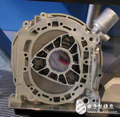
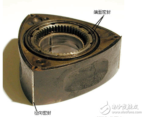
The rotor engine (Wankel Engine, Rotary Engine) was invented by the German Felix Wankel (1902-1988). Based on the previous research results, he solved some key technical problems. The first rotor engine was successfully developed. The rotary engine uses triangular rotor rotary motion to control compression and emissions, which is quite different from the linear motion of a conventional reciprocating piston engine. Comparison of a Rotor Engine with a Conventional Reciprocating Engine: Both a reciprocating engine and a rotary engine rely on the expansion pressure generated by combustion of an air-fuel mixture to obtain a rotational force. The institutional difference between the two engines is the way in which the expansion pressure is used. In a reciprocating engine, the expansion pressure generated on the top surface of the piston pushes the piston downward, and the mechanical force is transmitted to the connecting rod to drive the crankshaft to rotate. Rotor engine, for a rotary engine, the expansion pressure acts on the side of the rotor. Thereby one of the three faces of the triangular rotor is pushed towards the center of the eccentric shaft. This movement is carried out under the force of two components. One is the centripetal force pointing to the center of the output shaft, and the other is the tangential force that turns the output shaft. In this article, we will understand how the rotor engine works. Start with its basic working principle. Like the piston engine, the rotor engine is also the pressure generated by the combustion of air and fuel mixture. In a piston engine, this pressure is retained in the cylinder to drive the piston to move. The connecting rod and crankshaft convert the back and forth motion of the piston into a rotational motion that powers the car. In a rotary engine, the pressure generated by combustion is stored in a sealed chamber formed by a casing and a triangular rotor (which is used in place of a piston in the engine). Rotor and housing of a rotor engine in the Mazda RX-7: These parts replace pistons, cylinders, valves, connecting rods and camshafts in piston engines. The path of travel of the rotor is similar to that produced by a respirometer. The apex of the rotor is in contact with the housing to form three separate plenums. The rotor continuously moves around the combustion chamber, and the three volumes of gas alternately expand and contract. It is this expansion and contraction that draws air and fuel into the engine, then compresses the mixed gas, generates useful power as the gas expands, and finally exhausts the exhaust. Below we will go inside the rotor engine to understand its various parts. First we look at a new model equipped with a new type of rotor engine. Mazda has been a pioneer in the development of production vehicles using rotary engines. The RX-7, which was launched in 1978, is probably the most successful rotor-engine powered car. But before it appeared a series of rotor engine cars, trucks and even buses, the 1967 Cosmo Sport was the first one. The RX-7 exited the US market in 1995, but the rotor engine will return to the market in the near future. The Mazda RX-8 is a new car from Mazda that is equipped with the new RENESIS rotary engine. The engine won the 2003 International Best Engine Award. It is a naturally aspirated two-rotor engine that produces approximately 250 horsepower. The rotary engine has an ignition system and a fuel supply system similar to those of a piston engine. If you have never seen the internal structure of a rotor engine, you will be surprised because many parts are not known to you. The rotor has three convex faces, each of which is equivalent to a piston. Each convex surface of the rotor has a recess for increasing the displacement of the engine and accommodating more air and fuel mixture. The apex of each convex surface is a metal blade that forms an outer seal to the combustion chamber. There are metal rings on each side of the rotor for sealing the sides of the combustion chamber. The rotor has a set of internal gear teeth located at the center of one of the sides. They mesh with gears that are fixed to the housing. This engagement determines the path and direction of movement of the rotor within the housing.
Draw-wire sensors of the wire sensor series measure with high linearity across the entire measuring range and are used for distance and position measurements of 100mm up to 20,000mm. Draw-wire sensors from LANDER are ideal for integration and subsequent assembly in serial OEM applications, e.g., in medical devices, lifts, conveyors and automotive engineering.
Linear Encoder,Digital Linear Encoder,Draw Wire Sensor,1500Mm Linear Encoder Jilin Lander Intelligent Technology Co., Ltd , https://www.jilinlandermotor.com

Rotor engine introduction