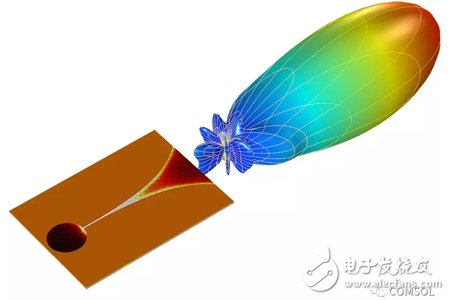
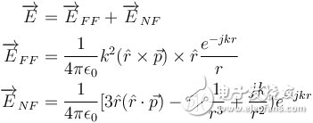
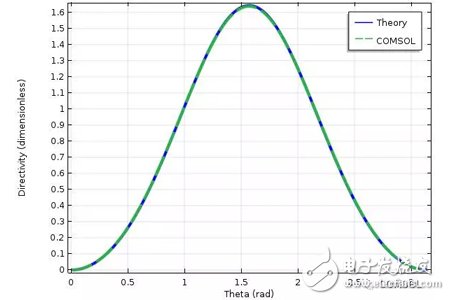
This article will open a new series of comprehensive blogs exploring multi-scale simulations of high-frequency electromagnetic fields. In the first article, we will introduce necessary support theories and definitions. Subsequent articles will explore how to use COMSOL MulTIphysics® software to perform multiscale simulations of high frequency electromagnetic fields in different scenarios. Multi-scale simulation is a challenging topic in modern simulation techniques. It refers to the problems that arise when a model has a distinct scale. For example, your mobile phone is about 15 cm long, but it needs to receive GPS information from satellites outside 20,000 km. It is not always easy to handle both lengths in a simulation. Simulation applications in weather, chemistry, and many other fields also encounter similar problems. Although multi-scale simulation is a general topic, we chose to focus on examples of antennas and wireless communications. When wireless data transmission through the antenna, the transmission process can be divided into three main phases: 1. The antenna converts the local signal into free space radiation. 2. The radiation travels away from the antenna, over a relatively long distance. 3. The other antenna detects radiation and converts it into a received signal. Modern communication transmits long-distance wireless data through an antenna. The two length scales in data transmission are the wavelength of radiation and the distance between antennas. Let's imagine a specific scenario: The FM radio has a wavelength of about 3 m. When you are listening to a radio in a car, it is usually more than 10 kilometers away from the radio tower. Many antennas (eg, dipoles) are similar in size to wavelength, so it is not necessary to consider the antenna size as a different length scale. To sum up, the dimensions involved include: the length scale of the transmitting antenna, another length scale of the signal transmitted from the source to the destination, and then the original length scale of the receiving antenna. Before dealing with multiple scales in the same high-frequency electromagnetic model, we first revisit some of the most core equations, terms, and considerations. The Friis transmission equation calculates the received power of line-of-sight communication between two antennas separated by a lossless medium. The formula is Among them, the subscripts r and t distinguish the transmitting and receiving antennas, G is the antenna gain, P is the power, Γ is the reflection coefficient of the impedance mismatch between the antenna and the transmission line, p is the polarization mismatch factor, and λ is the wavelength, r is the distance between the antennas, which is associated with the so-called free-space path loss, and θ and φ are the corner coordinates of the two antennas. Note that we explicitly introduced two impedance mismatch terms, so: · Pt refers to the power provided by the transmitting antenna to the transmission line · Pr refers to the power received by the receiving antenna from the transmission line Many texts indicate the derivation of the Frith equation, so we skip over here. Transmit antenna and receive antenna gain visualization. When using the Friction equation, we must understand the direction of the antenna in order to obtain the correct gain parameters. The distance between the antennas is r. Spherical coordinates In the following, we discuss spherical coordinates (r, θ, φ) because the spherical coordinates are extremely suitable for studying antenna radiation, and we will use them repeatedly in the following text. Starting from Cartesian coordinates (x, y, z), we can easily use the following expression. For convenience, we used the real COMSOL MulTIphysics commands -- sqrt(), acos(), and atan2(), rather than their mathematical notation. When creating simulations, we will also use spherical unit vectors The given point is simultaneously expressed using Cartesian coordinates (x, y, z) and spherical coordinates (r, θ, Φ). The unit vector of spherical coordinates is also displayed in the picture. Please note that the unit vector of spherical coordinates is a function of position. PoynTIng vector and radiation intensity We are usually very interested in the radiated power of the antenna. The unit of power flux is W/m2, using the complex Poynting vector To represent. Many texts relating to antennas also use radiation intensity, which is defined as the radiated power per solid angle in units of W/steradian. In mathematics, its formula writing To make the reader clearer, we have introduced two idioms here: Often used in electrical engineering, physicists are usually more familiar with After that, we integrate the radiant intensity at all angles to calculate the radiant power. Gain and Direction Gain and directionality are similar in that they both quantify the radiated power in a specific direction, except that the gain correlates the radiated power in a specific direction with the input power, and the directionality correlates it with the total radiated power. . More simply, gain can explain dielectric loss and conduction loss, while directionality cannot. In mathematics, gain and directionality are expressed as with Pin is the power received by the antenna and Prad is the total radiated power. Although both physical quantities are significant, the gain can explain the material loss in the antenna and is generally more practical. Taking into account its generality and practicality, we also referred to the "IEEE Standard Definition Terms for Antennas". The gain (in a given direction) is defined as: "Received at the antenna. The ratio of radiation intensity in a given direction to the intensity of radiation received in a condition where the radiated power is isotropic." For the definition of gain, IEEE added three annotations: 1. "Gain does not include losses due to impedance and polarization mismatch." 2. "The radiation intensity of isotropic radiant power is equal to the power received by the antenna divided by 4π". 3. "If the antenna has no dissipative losses, its gain is equal to its directivity in any given direction." Gain, actual gain, and impedance mismatch In reality, the true antenna will be connected to the transmission line. The impedance of the antenna and the transmission line may not be the same, so there may be a loss factor due to the impedance mismatch. The actual gain refers to the gain when considering the impedance mismatch. In mathematics, the actual gain is expressed as among them For the reflection coefficient of the transmission line theory, Zc is the characteristic impedance of the transmission line and Z is the impedance of the antenna. When using a lumped port with characteristic impedance in COMSOL Multiphysics, the calculated far-field gain corresponds to the actual gain defined by the IEEE (Institute of Electrical and Electronics Engineers). We must mention this explicitly because the definition of gain has changed several times over the past few decades. As of the release of COMSOL Multiphysics 5.3 in 2017, the COMSOL software will change the variable names as defined by the IEEE. The actual gain and electric field of the Vivaldi antenna were simulated using COMSOL Multiphysics and the "RF module". You can get the teaching model of the Vivaldi Antenna in Case Download. Until now, the terms we discussed corresponded to radiating antennas, but they were also generally applicable to receiving antennas. In the above, we paid more attention to the reason for the launch because the antenna usually obeys the reciprocity theorem (Lorentz reciprocity theorem is a necessary chapter of most antenna textbooks). The meaning of reciprocity is that in a particular direction, the gain of the antenna is the same regardless of whether the signal is transmitted in or out of this direction. In practical research, you can use a single simulation of the transmitting antenna to calculate the gain in any direction, which is much simpler than simulating the receiving process in each specified direction. When discussing the receiving antenna, we often want to calculate the received power of the incident signal. The specific method is to use the effective area of ​​the antenna Multiplied by the incident power flux, taking into account the impedance mismatch of the transmission line. As expected, it is strikingly similar to several of the Frithian transmission equations. Transmitter example: perfect electric dipole Today, we will discuss one type of transmitter: the perfect electricity dot dipole. You may see it in various literatures as perfect, ideal, or infinitely small dipoles. This transmitter is often used to characterize the radiation of small electric antennas. The field solution equation is among them An exploded view of each region of the electromagnetic field generated by the small antenna. In the above equation, 1/rn has three factors. The 1/r2 and 1/r3 terms are more important near the source, and the 1/r terms dominate over larger distances. Although electromagnetic fields are continuous, people generally divide different areas of the field according to their distance from the source. The figure above shows a field distribution of small antennas. In fact, there are other idioms that are suitable for describing the size of kr. Later, we will show how to calculate the field at any distance from a given source, but the most critical area of ​​antenna communication is the farthest field or radiation area that is farthest from the source. In this area, the field appears as a spherical wave ~exp(-jkr)/r In the form, after which we will use this fact. Now we will split the E-field equation into two items. For the sake of simplicity, we refer to the 1/r term as the far field (FF) and the 1/r2 and 1/r3 terms as the near field (NF). As mentioned above, we can work on all corners Integrate to calculate radiant power in watts. Please note that only the far field term contributes to the integral, which is the main reason why the antenna has practical significance for the antenna engineer. The total power of point dipole radiation is Where Z0 is the impedance of free space and c is the speed of light. The maximum gain is 1.5, which is in a plane perpendicular to the dipole moment (eg Explanation of the unit: We are based on the dipole moment of Coulomb*meter (Cm) The traditional definition of the above writes the expression above. Antennas and engineering texts often use Ampere* Am to specify infinitesimal current dipoles. COMSOL Multiphysics follows engineering conventions. The above two definitions are related by the time derivative, so when performing the equation in the COMSOL software, the dipole moment should be Receiver example: half-wavelength dipole We use an ideal conductor-half-wavelength dipole as a receiving antenna. Many texts have explored infinitely thin conductors, its impedance ≈ 73Ω, and its directionality is . It is worth mentioning that the impedance of this antenna is different from that of an antenna with a radius. The length of the receiving antenna we have discussed is 0.47 λ and the ratio of length to diameter is 100. Using these values, our simulations obtained an impedance of ≈ 733jΩ, which is close to the impedance of an infinitely thin wire and is in good agreement with experimental values. Unfortunately, there is no theoretical value to compare this figure, but this emphasizes the need for numerical simulation of antenna design. The following figure compares the directivity of an infinite dipole and dipole antenna simulation. Because the antenna is lossless, this is equivalent to the antenna gain. You can download the dipole antenna model by clicking "Read original". Compare the functional relationship between the directivity of two half-wavelength antennas (z direction) and θ. The COMSOL Multiphysics® simulation model is a cylinder with a small radius. The theoretical model is an infinitely thin antenna. Now we can use the Fries transmission equation to calculate the power of the perfect point dipole emission and the power received by the half-wavelength dipole antenna. When using equations, we only need to understand the gain and impedance mismatch (or actual gain), wavelength, distance between antennas, and input power. We chose to use the electric dipole, so we can obtain the dipole moment instead of the input power and impedance mismatch. To solve this problem, we can remove the impedance mismatch term and replace the input power with the radiated power of the perfect electric dipole—in fact, the input power is equal to the radiated power. If we assume that both the transmitter and the detector are located in the xy plane, they are in polarization-matched state separated by 1000 λ, and Conclusion In this blog, we introduce the concept of multi-scale simulation and discuss related terms, definitions, and theories that need to be understood before modeling. For professionals with a profound background in electromagnetics and antenna design, this may be a quick review. If you are unfamiliar with the concepts presented in this article, we strongly recommend that you read a book that introduces classic electromagnetic or antenna theory. The sound quality of small speakers is also good. It does not have the same large speakers and power as HIFI speakers, and its sound quality cannot compete with large speakers due to physical limitations. But for the vast majority of users who are not golden ears, the use of small speakers with tablets and mobile phones is sufficient to meet their hearing needs. Wireless Retro speaker,Waterproof Retro speaker, Portable Vintage speaker,Rechargeable Vintage speaker Shenzhen Focras Technology Co.,Ltd , https://www.focrass.com


![]() Cartesian components.
Cartesian components. 
![]() with
with ![]() The Cartesian component can also achieve similar tasks, but
The Cartesian component can also achieve similar tasks, but ![]() For us is the most important. In the follow-up blog that introduces ray optics, we will explore this issue.
For us is the most important. In the follow-up blog that introduces ray optics, we will explore this issue. 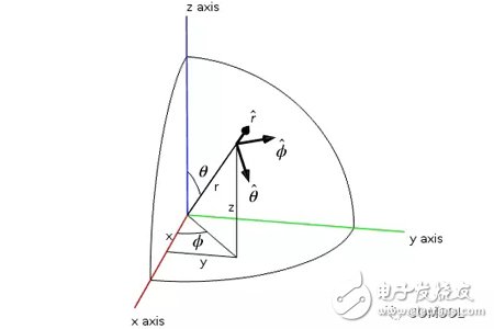
![]()
![]() .
. ![]()
![]() .
. 
 .
. ![]() ,
, ![]()

 .
. 
![]() The dipole moment of the radiation source (not to be confused with the polarization mismatch), k is the wave vector of the medium.
The dipole moment of the radiation source (not to be confused with the polarization mismatch), k is the wave vector of the medium. 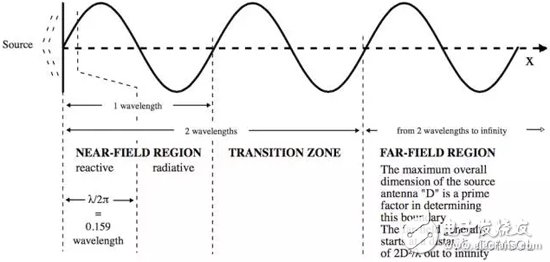

 ,
, ![]() The xy plane in the middle dipole is isotropic.
The xy plane in the middle dipole is isotropic. 
![]() Multiply by the factor jω to obtain an infinitesimal current dipole.
Multiply by the factor jω to obtain an infinitesimal current dipole. 

![]() The dipole moment of the emitter in the middle is 1 Am, so the calculated value of the Fries equation for the received power is 380 μW. We will simulate the received power values ​​in Part 3 of this series to verify the simulation technique. Then we can confidently extract the results from the simulation and introduce the complexity that the Fries equation cannot explain.
The dipole moment of the emitter in the middle is 1 Am, so the calculated value of the Fries equation for the received power is 380 μW. We will simulate the received power values ​​in Part 3 of this series to verify the simulation technique. Then we can confidently extract the results from the simulation and introduce the complexity that the Fries equation cannot explain.
For Bluetooth retro speakers, I personally think that when many people buy speakers, the appearance is the first priority and the function is second.
We focus on retro Bluetooth speakers,It has high energy density, mini size, light weight and diversified shapes;Excellent fast charging performance, support fast charging and other excellent features
with a brand-new design, showing retro nostalgia without losing fashion. It uses a 2.5-inch speaker and has many functions such as FM radio, Bluetooth fast connection, multi-mode switching, and HIFI high fidelity. Wireless Bluetooth 4-10 hours of playback (at 50% volume), which adds to its unique charm.