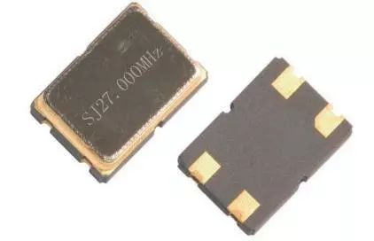
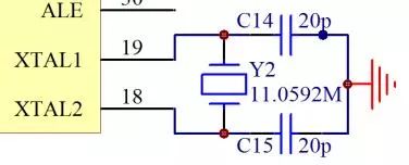
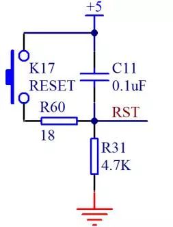
During the learning process, many indicators are directly used as conceptual indicators. For example, we say that +5 V stands for 1, GND stands for 0, and so on. But the voltage value in the actual circuit is not completely accurate. What are the allowable ranges of these indicators? As we learn more and more, we must slowly develop the ability to read data books. For example, when we want to use the STC89C52RC, find its data sheet on page 11 and see item 2 - Operating Voltage: 5.5 V to 3.4 V (5 V Microcontroller). This place shows that the normal operating voltage of the microcontroller is a range. Value, as long as the power supply VCC can operate normally between 5.5 V and 3.4 V. If the voltage exceeds 5.5 V, it is absolutely not allowed. It will burn the SCM. If the voltage is lower than 3.4 V, the SCM will not be damaged, but it will not work properly. . In this range, the most typical and commonly used voltage value is 5V, which is the name of the name “5 V Microcontroller†in parentheses. In addition, there is a commonly used single-chip microcomputer with an operating voltage range of 2.7 V to 3.6 V and a typical value of 3.3 V, which is the so-called “3.3 V microcontrollerâ€. In the future, as people contact more devices, we will have a deeper understanding of this point. Now let's learn more about this. If you open the 74HC138 datasheet, you will find that there is a table on the second page of the 74HC138 manual. The working voltage range of the 74HC138 is written above. The minimum value is 4.75V and the rating is 5V. It is 5.25 V. It can be seen that its operating voltage range is 4.75 V to 5.25 V. The purpose of this place is to let everyone know clearly. One of the most important and authoritative ways to obtain device operating parameters is to consult the data sheet of the device. Crystal oscillators are generally classified into two types: passive crystals and active crystals. Passive crystals are generally called crystals, and active crystals are called oscillators. The active crystal oscillator is a complete resonant oscillator. It uses the piezoelectric effect of the quartz crystal to start the oscillation. Therefore, the active crystal oscillator needs to be powered. When we do the active crystal oscillator circuit, we do not need to connect other devices. Just give It supplies power, it can actively generate the oscillation frequency, and can provide a high-precision frequency reference, and the signal quality is also better than the passive signal. The passive crystal itself cannot oscillate. It requires the oscillation circuit inside the chip to work together to oscillate. It allows different voltages, but the signal quality and accuracy are worse than the active crystal. For relative prices, passive crystals are much cheaper than active crystals. There will usually be a capacitor on both sides of the passive crystal. Generally, the capacitance is selected between 10 pF~40 pF. If the manual has a specific capacitor size, the capacitor must be selected according to the requirements. If the manual does not require, we use 20 pF is a better choice. This is a long-term experience and it has extremely universal applicability. Let's recognize the appearance of the two more commonly used crystals, as shown in Figure 8-1 and Figure 8-2. Figure 8-1 Active crystal oscillator Figure 8-2 Passive crystal oscillator The active crystal oscillator usually has 4 pins, VCC, GND, crystal oscillator output pins and an unused floating pin (some crystals also use this pin as an enable pin). The passive crystal has 2 or 3 pins. If it is 3 pins, the middle pin is the crystal shell. When using it, it must be connected to GND. The pins on both sides are the 2 pins of the crystal. The two pins function identically, like the two pins of the resistor, with no positive or negative points. For the passive crystal oscillator, use two crystal pins on our microcontroller to connect it, and the active crystal oscillator is only connected to the input pin of the crystal oscillator of the SCM. The output pin does not need to be connected, as shown in Figure 8- 3 and Figure 8-4. Figure 8-3 Passive crystal connection Figure 8-4 Active Crystal Oscillator Connection Let's first analyze the reset circuit on the KST-51 development board, as shown in Figure 8-5. Figure 8-5 MCU reset circuit When this circuit is in a steady state, the capacitor acts as a DC isolation, isolating the +5 V, while the left reset button is in the pop-up state, and there is no voltage difference in the lower part of the circuit, so the following part of the button and capacitor C11 The potential is equal to GND, which is 0 V. Our one-chip computer is a high level reset, low-level normal work, so the normal working voltage is 0 V, no problem. Let's analyze the moment from no electricity to power up. The voltage above the capacitor C11 is 5 V and the bottom is 0 V. According to our knowledge of junior high school, the capacitor C11 is to be charged, positive ions are charged from above, negative electrons are GND is charged up. At this time, the capacitor is equivalent to a wire for the circuit. All voltages are added to the R31 resistor. The voltage at the RST port is 5 V. As the capacitor charges more and more, it will be full. When the current is getting smaller and smaller, the voltage at the RST port is equal to the current multiplied by the resistance of the R31, and it will become smaller and smaller until the capacitor is fully charged and there is no more current on the line. The potentials of RST and GND are equal to 0 V. From this process point of view, we add this circuit. After the microcontroller system is powered on, the RST pin will remain high for a short time and then go low. This process is the power-on reset process. What is the appropriate amount of this "short period of time"? Each type of MCU is not exactly the same, and 51 MCU manuals are written for a duration of not less than 2 machine cycles. The reset voltage value is not exactly the same for each type of microcontroller. We use the normal value of 0.7 VCC as the reset voltage value. The reset time calculation process is more complicated. I only give you a conclusion here. The time is t=1.2 RC, and the R we use is 4700. Europe, C is 0.0000001, then calculate t is 0.000564 seconds, that is, 564 us, which is much larger than 2 machine cycles (2 us). Generally, enough margin is left in the circuit design. The key reset (ie, manual reset) has two processes. Before the key is pressed, the voltage of RST is 0 V. When the key is pressed, the circuit is turned on and the capacitor is discharged instantaneously. The RST voltage value changes to 4700 VCC/ (4700+18), will be in a high reset state. When the button is released, it is similar to the power-on reset. First, the capacitor is charged and the current gradually decreases until the RST voltage changes to 0 V. We usually press the button for a few hundred milliseconds, which is enough time for the reset. At the instant when the button is pressed, the 5 V voltage across the capacitor (not between the 5 V and GND of the power supply) will be directly connected. At this moment, there will be a momentary high-current impact, which will cause electromagnetic interference in the local area. To suppress the interference caused by this large current, we hereby put an 18 ohm resistor into the capacitor discharge circuit to limit the current. If some students already want to start designing their own circuit boards for DIY, then the design of the microcontroller has already had enough theoretical basis, and it is worth considering. The students with relatively weak foundations should not worry any more. They should continue to follow and study. After completing the courses, they must continue their operations. They should not be mistaken to cut the firewood. Other household electric appliance gree , https://www.greegroups.com


